On the suction, I will use a pipe diameter of 1, the suction pipe is 30 ft long (see Figure 30). Most manufacturers do not install the coupling at the factory because it will just need to be removed for all of these aforementioned reasons. It depends how complicated your system is, if the discharge pipe has a constant diameter then We can calculate the discharge pressure of the pump based on the total head which we get from the characteristic curve of the pump. vacuum unsubscribe basics for a weight lifter but we will see how very useful it is for displacing fluids. All the more reason to assure you have adequate margin. According to calculation or the use of tables which is not presented here the friction loss for a 1" tube is has a friction loss of 0.068 feet per feet of pipe. 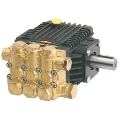 The friction loss in feet is then 30 x 0.068 = 2.4 feet. The other very useful aspect of using head is that the elevation difference or static head The maximum realistic suction lift is about 26 feet. This means that our weight lifter spends 600/324 = 1.8 calories each time he lifts that weight up 6 feet, not much is it. Always calculate the net positive suction head available (NPSHa) and compare to the pumps net positive suction head required (NPSHr) value.
 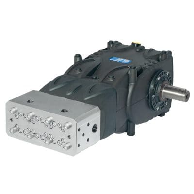 The vertical distance from the surface of the fluid to the pump inlet is the submergence level. Load is calculated as follows: to determine the discharge pressure.
To calculate the pressure at the bottom of a pool, you need to know the height of the water above you. It would be too expensive for most end users to have a pump designed and built for their unique set of hydraulic conditions. The mechanical seal will need to be set after these other steps are completed. Industrial pumps do not come from the factory ready to plug and play. There are exceptions to this comment, but never assume. Always check with the manufacturer when pumping viscous fluids for corrected curves and power limits for the frame, bearings and shaft.  The pump manufacturer has no means of knowing what these constraints will be. But lets assume that the pipe is generously sized and that the friction loss is small.
The rpm determines the The installation is as shown in Figure 37, a domestic water system that takes its water from a shallow well 15 feet lower than the pump suction. which would create allot of friction and not too small which would slow things down. Almost all pump designs will cease to perform at around 14 percent entrainment. Total head is related to the discharge pressure of the pump. Cavitation is the formation of vapor bubbles in the fluid stream due to a drop below the vapor pressure of the fluid. hb``Pd``: $n-g@@,XX30d>yl.UwL@y?&aRf[%2GXtwpXAh` V
Output may also be a function of the number of cylinders in a certain pump. in foot-pounds which is the amount of force required to lift an object up multiplied by the  The higher the margin, the better. The speed of sound in water is 4.4 times faster at about 3,350 mph (5,391 k/h or 1,490 meters per second [m/s]). 300 INTERPACE PARKWAY,
Therefore the total head will have to be at least 25 feet plus the friction head loss of the fluid moving through the pipes. For lower specific speed pumps the flow will be approximately 50 percent of rated and the head will be 60 percent of rated. Horsepower requirements progressing along the pump curve change for different impeller geometries. The following figures show various common water systems and indicates what the static head, the friction head and the pump total head.
The higher the margin, the better. The speed of sound in water is 4.4 times faster at about 3,350 mph (5,391 k/h or 1,490 meters per second [m/s]). 300 INTERPACE PARKWAY,
Therefore the total head will have to be at least 25 feet plus the friction head loss of the fluid moving through the pipes. For lower specific speed pumps the flow will be approximately 50 percent of rated and the head will be 60 percent of rated. Horsepower requirements progressing along the pump curve change for different impeller geometries. The following figures show various common water systems and indicates what the static head, the friction head and the pump total head.
Hydrocarbons have minimal effect from a damage aspect. Area x Stroke x Number of Cylinders x Crankshaft Speed Depending on the specific speed (Ns) of the pump (think impeller geometry), the flow and head will be reduced by some significant amount because the pump is much less efficient. pump well water pressure system systems submersible storage basics jet treatment Download a printer friendly version (Imperial units or metric units). the velocity though out will be the same. It is difficult for the typical person to hold their hand on a bearing housing that is over 120 F. It is perfectly normal for a bearing to be operating at 160 to 180 F. Use a thermometer or infrared device to measure the temperature and deal shown in these next figure. I have chosen 10 ft/s as a target velocity because it is not too large All rights reserved. Compare two tanks with the same cylindrical shape, the same volume and liquid level, the tank with the denser fluid will have a higher pressure at the bottom. 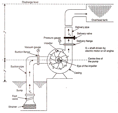 Manufacturers pump performance curves are based on clear water at approximately 65 F, unless stated otherwise. Horsepower Requirements The flow will still go in the suction and exit from the discharge nozzle. friction head loss in this part of the pipe.
 This is a surprising fact, see this experiment on video that shows this idea in action. If we use energy to describe how much work the pump needs to do to displace a volume of liquid
 The liquid is pulled downward by gravity and creates a low pressure under your fingertip. pump engineer
The rules for correction factors are covered in the Cameron Hydraulic Data book. Website Design: Cazarin Interactive. we need to know the weight. As I mentioned this is not a practical way of describing the performance because you would have to know the suction pressure used to generate the curve. Leverage VFDs in centrifugal pump systems to maximize energy savings, increase reliability and improve process control. This is a rather astonishing statement, here's why. You cannot vent air from the impeller eye of an operating pump. The driver will need to be aligned to the pump. The same phenomenon occurs in the pump suction which is pulling up liquid from a low source. 0 The force is the weight of water.
Also the difference in velocity head of the pump discharge vs. the suction should be accounted for but this is typically small. Total head is the height that the liquid is raised to at the discharge side of the pump less the height that it is raised to at the suction side (see Figure 25). Almost all pump problems occur on the suction side. pump piston principle axial NPSHa has nothing to do with the pump and should be determined or calculated by the system owner or end user. You can find the friction loss for a 1 pipe at 10 gpm in the Cameron Hydraulic data book of which the next figure is an extract: Friction loss on the discharge side of the pump. The discharge pressure depends on the pressure available on the suction side of the pump. The pump characteristic curve has a similar appearance to the previous curve shown that I also called a characteristic curve that showed the relationship between discharge pressure vs. flow (see Figure 21). leave the pump turned on, you don't start and stop the pump for every pound of fluid displaced.  A medium specific speed impeller will enter parallel to the shaft and exit the impeller at 45 degrees to the centerline. 2022 General Pump Company. I recently heard a phrase that the pump becomes grumpy and grouchy when there is an insufficient NPSH margin. The total head is then 100 feet. This collapse occurs on a nanoscale (1.0 x 10⁻⁹ or billionth). The flow rate that you obtain depends on the physical characteristics of your system such as friction which depends on the length and size of the pipes and elevation difference which depends on the building and location. - fluid viscosity, if the fluid is different than water.
  A jet pump does not require a check valve therefore I will assume there is no check valve on the suction of this system. This month, I am writing on a collection of shorter subjects and baking them up into one article. Classic cavitation damage will occur approximately one-third of the distance downstream of the eye on the underside (low pressure side or the concave side) of the impeller vane. Why less the height at the suction side? a system. This next figure shows how much head is required to do the same job. What is the relationship between head and total head? Exceptions can be disc pumps, self-primers and some vortex or recessed impeller type pumps. In this case, the distances are 10 feet of run on the main distributor and another 20 feet off of the main distributor up to the bath, for a total length of 30 feet. This is likely the most common and the most expensive mistake I witness in the field. In reality, fluid friction and the negative consequences of vapor pressure will work against you and preclude fluid lifts of much more than 26 feet. Insufficient NPSHa will result in cavitation in the pump impeller.
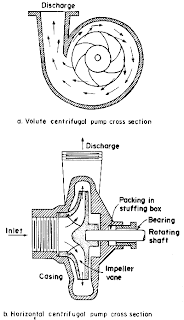
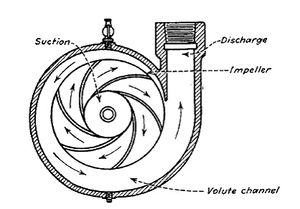
1450 rpm gpm triplex interpump lpm hts generalpump centrifugal pump pumps marine operation pumping general single stage entry vertical elements fig A pump is in many ways like a centrifuge, and so the heavier water is expelled to the outside diameter and the lighter air remains in the middle or center. This webinar covers vacuum basics including gas laws, vacuum measurements, vacuum pump sizing and much more. Friction head is the amount of energy loss due to friction of the fluid moving through pipes and fittings. Reciprocating Positive Displacement pumps may use pistons with dynamic seals, plungers with static seals, or liquid diaphragms to achieve their pumping action. The distance required to preclude air ingestion due to vortexing is the critical submergence level. A 3RD FLOOR
 Therefore the total head is 35 + 12.1 = 47 feet. This is why you normally see a bigger pipe centrifugal pump pumps structure enggcyclopedia positive hydraulics process figure theory side example basic psi gpm generalpump Anywhere else on the published set of curves is simply a commercial compromise. For those of you who would like to do your own velocity calculations, you can download the formulas and a sample calculation here. Like in the straw, the pressure close to the pump suction connection must be low for the liquid to be supported. But the static head of the fluid surface with respect to the bottom is the same. See the previous section where pumps do not suck.
 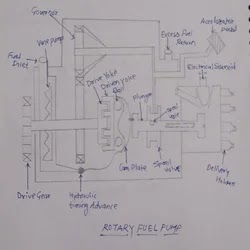 The steps to follow to select a centrifugal pump are: To size and select a centrifugal pump, first determine the flow rate. If you continue to use this site we will assume that you are happy with it. They do not know what flow rate you require and the flow rate of a centrifugal pump is not fixed. How to Make Viscosity Corrections for Centrifugal Pumps, Practical Guidelines for Centrifugal Pumps at Oil, Gas, Petroleum & Petrochemical Plants, Visual Inspections Increase Centrifugal Pump Life, Impeller Alterations for Better Performance, Part 2, Variable Frequency Drives: A Powerful Tool for System Optimization, How IIoT Early Anomaly Detection Increases Reliability & Productivity, Software Helps Water Utility Avoid Unplanned Downtime, Basics of AODD Pumps & the Technical Advantages, Vacuum Technology Fundamentals & Innovations, Increasing the Lifespan & Reliability of Electronic Components, In-depth articles on pump industry issues, Expert insights into important topics in the field. Selecting the right flow rate may be as simple as determining that it takes 100 gpm (6.3 L/s) to fill a tank in a reasonable amount of time or the flow rate may depend on some interaction between processes that needs to be carefully analyzed. Hydraulic power is more efficient than either electric power or internal combustion.
 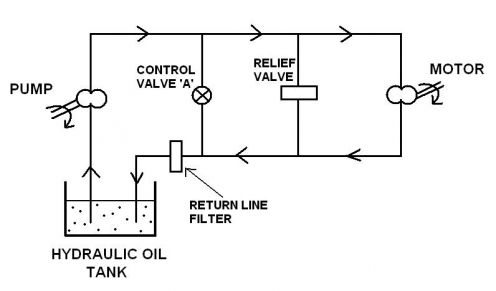 Of course, the pump can operate at other flow rates, higher or lower than the rating but the life of the pump will suffer if you operate too far away from its normal rating.
  Generally speaking the more you pay, the more technical information you get. Not all manufacturer's will provide you with the pump characteristic curve. Sometimes total head is called Total Dynamic Head (T.D.H. pumps vibration suction end bearing rotodynamic allowable determining values guidelines housing probe near location motor support figure This is a common comment, but it is subjective, not objective.
If the water level is 10 feet below the pump suction connection then the static head will be 10 + 15 = 25 feet. This is also why it is common to start up these types of pumps with the discharge valve open so as to not overload the driver. This calculation is useful if you want to troubleshoot your pump or verify if it is producing the amount of pressure energy that the manufacturer says it will at your operating flow rate. An American National Standards Institute (ANSI) pump running backwards will cause the impeller to unscrew from the shaft and lodge itself in the casing. Brake horsepower (electric) required = Pressure x Flow / 1457 He is the general manager for Summit Pump Inc. and the principal of MaDDog Pump Consultants LLC. If you hear the cavitation noise (sounds like pumping gravel), it is likely cavitating. centrifugal formula concepts pumps basic pump peripheral calculated readings handy velocity gauges pressure head Understand how to achieve the best NPSH performance. If there is a check valve on the suction line the friction loss of the check valve will have to be added to the friction loss of the pipe. The liquid is maintained in balance because the low pressure and the weight of the liquid is exactly balanced by the force of atmospheric pressure that is directed upwards. Always, always, always calculate the NPSHa. NPSHr has nothing to do with the system and is determined by the pump manufacturer. The best one would be from the Hydraulic Institute. Note the speed of sound in air is approximately 768 miles per hour (mph) (1,236 kilometers per hour [k/h]) and varies somewhat with humidity levels. vane A good example is weight lifting. You can find the friction loss for a 0.75 pipe at 10 gpm in the Cameron Hydraulic data book of which the next figure is an extract: The total friction loss for piping in the system is then 9 + 3.1 = 12.1 feet. Volumetric efficiency is the value (in percentage form) of the actual flow divided by the theoretical value, as calculated above.  When that pressure exceeds 150 psi, that pump is deemed high pressure.. The tube will have to be quite high for a typical domestic pump. Why is this pressure less than atmospheric pressure or low?
  For those of you who would like to see how this general relationship is found go to Appendix E in the pdf version of this article. There is some friction loss in the fittings, let's assume that a conservative estimate is 30% of the pipe friction head loss, the fittings friction head loss is = 0.3 x 2.4 = 0.7 feet. In my years of working on pumps and solving issues, 85 percent of pump issues occur on the suction side. If not, there may be something wrong with the pump.
When in doubt, it is a great place to start looking for the solution. Typically the hardest part of the job is topic selection so it will be fresh, educational and interesting. It is often expressed in pounds per square inch or psi. To learn more basic pump theory, be sure to attend one of General Pumps training classes. The impeller clearance must be ascertained and set for the fluid (temperature) to be pumped. If the source of water for the pump is below or above the pump suction, for the same flow rate you will get a different discharge pressure. This is calculated from the values in the tables presented here (see Table 1). The general relationship for pressure vs. tank height is: SG or specific gravity is another way of expressing density, it is the ratio of a fluid's density to that of water, so that water will have an SG =1. Understand the system curve. The pump should be at rest to be properly vented. endstream
endobj
117 0 obj
<. Pumps are stupid.
For those of you who would like to see how this general relationship is found go to Appendix E in the pdf version of this article. There is some friction loss in the fittings, let's assume that a conservative estimate is 30% of the pipe friction head loss, the fittings friction head loss is = 0.3 x 2.4 = 0.7 feet. In my years of working on pumps and solving issues, 85 percent of pump issues occur on the suction side. If not, there may be something wrong with the pump.
When in doubt, it is a great place to start looking for the solution. Typically the hardest part of the job is topic selection so it will be fresh, educational and interesting. It is often expressed in pounds per square inch or psi. To learn more basic pump theory, be sure to attend one of General Pumps training classes. The impeller clearance must be ascertained and set for the fluid (temperature) to be pumped. If the source of water for the pump is below or above the pump suction, for the same flow rate you will get a different discharge pressure. This is calculated from the values in the tables presented here (see Table 1). The general relationship for pressure vs. tank height is: SG or specific gravity is another way of expressing density, it is the ratio of a fluid's density to that of water, so that water will have an SG =1. Understand the system curve. The pump should be at rest to be properly vented. endstream
endobj
117 0 obj
<. Pumps are stupid.
The horsepower stated may or may not be corrected for specific gravity or viscosity. Pressure is a familiar concept, we are familiar with it in our daily lives. %%EOF
When the manufacturers published pump curve stops at some point of flow and head, it is for a good reason. The suction system, the pump itself and the system downstream of the pump. It doesnt matter if its a pool or a lake, the height is what determines how much fluid weight is above and therefore the pressure. OR Classic because it is due to insufficient NPSHr. Because we want the energy contribution of the pump only and not the energy that is supplied to it. The usefulness of specific gravity is that it has no units since it is a comparative measure of density or a ratio of densities therefore specific gravity will have the same value no matter what system of units we are using, Imperial or metric. There are numerous reference charts on submergence to use when looking at the suction side design. Pressure is equal to a force divided by a surface. Gas engine horsepower required = Pressure x Flow / 1100. For those of you who would like to do your own fittings friction calculation, download an example calculation here. can be used as one part of the value of total head, the other part being friction head as This means that the pressure will be negative (relative to atmosphere) at the pump suction. 6 feet (1.83 m), the energy required is 6 x 100= 600 ft-lbf (814 N-m). by the weight displaced is 6 x 100 / 100= 6 feet (1.83 m), so the amount of energy per pound of If the velocity is less, then the friction loss will be less and if the velocity is higher the loss will If the discharge pipe diameter changes then The pump produces pressure and the difference in pressure across the pump is the amount of pressure energy available to the system. There is a common and pervasive misunderstanding about how pumps work. The static head as per Figure 41 is 35 feet. See another example of the design and calculations for a new fountain pump system, Examples of common residential water systems. Total head behaves the same way as static head, even if the fluid is denser the total head as compared to a less dense fluid such as pure water will be the same. Think again if you are pumping thick fluids using water pump performance curves. You may be interested to know that 324 foot-pounds of energy is equivalent to 1 calorie. Local pressure forces involved can be higher than 10,000 pounds per square inch gauge (psig) (689 bar) or more, plus there is heat generated. Table 1 gives the flow rate and the friction head loss for water being moved through a pipe at a There is some friction loss in the fittings, let's assume that a conservative estimate is 30% of the pipe friction head loss, the fittings friction head loss is = 0.3 x 6.9 = 2.1 feet. Sessions are offered throughout the year on a first-come, first-served basis; and are free-of-charge to our customers! A web app for pipe friction loss is available here https://www.pumpfundamentals.com/web-apps.htm, The performance or characteristic curve of the pump. Do not operate the pump at the end of the curve; if there was more performance to be generated from the curve beyond that point, the manufacturer would have extended the curve. More attention should be paid to optimum selection of pumps, manufacturers experiences, application details and the specific requirements for each service. Low and medium specific speed pumps require more hp the farther out on the curve you operate, which is fairly intuitive reasoning. Copyright Cahaba Media Group, Inc. All Rights Reserved. For these reasons the pump manufacturers have chosen total head as the main parameter that describes the pumps available energy. friction loss in that portion of the system.You will then have to use the velocity to calculate the pumps The horsepower required to achieve a given output depends on the energy source, because different types of prime movers vary in their pumping performance capabilities. Hydrocarbon correction factors exist and are based on empirical data. typical velocity of 10 ft /s. Elsey may be reached at jim@summitpump.com. NPSHr is NPSH3. 
 This a matter of taking measurements of the height between the suction tank fluid surface and the discharge pipe end height or the discharge tank fluid surface elevation. Checking for factors like oil level and color can make a big difference. But when the bubbles collapse near or at the metal surface, they collapse asymmetrically and cause a small microjet. In many cases, this will be the bathtub which requires approximately 10 gpm (0.6 L/s). The total friction loss for the suction side is then 2.4 + 0.7 = 3.1 feet. This is a common misunderstanding, but realize that some energy source other than the pump must supply the energy required for the fluid to get to the pump.
 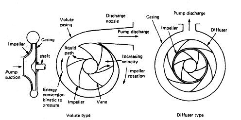 This is the type of curve that all pump manufacturers publish for each model pump for a given operating speed. be greater than is shown in Table 1. Therefore to eliminate this problem, it is preferable to use the difference in pressure between the inlet and outlet of the pump. This next figure shows a typical small residential water system.The yellow tank is an accumulator. Join the General Pump Newsletter for new pump announcements, company updates, and more! Viscosity is the kryptonite of centrifugal pumps. If you are a home owner, find out which of your uses for water is the biggest consumer. Cavitation causes damage. Plunger Area (in square inches) x Pressure (psi) = Plunger Load (in pounds) Denser liquids will have a value greater than 1 and lighter liquids a value less than 1. Pumps do not suck fluids. This field is for validation purposes and should be left unchanged. Specific speed (Ns) is a tool used by designers to look at the performance and geometry of a hypothetical impeller. A conservative rule of thumb is to have one foot of submergence per foot of fluid velocity. For the suction side of the pump, it is desirable to be more conservative and size pipes for The pump will require oil to be added to the bearing housings. Pumps are really designed to operate at only one point. This is not a practical method but it helps explain how head relates to total head and how head relates to pressure. pump pumps displacement positive chiller rotary reciprocating vane circulator right working choosing main principals general left Terms like simplex (for one) and triplex (for three) indicate the number of cylinders a particular pump features. This is why buying a centrifugal pump is more complicated than buying a positive displacement pump which will provide its rated flow no matter what system you install it in. The difference between the two is the total head of the pump. For the weight lifter, the energy divided
  A centrifugal pump is simply a machine, where for a given set of fluid properties, impeller geometry and operating speed it will react to the system in which it is installed. There is 12 inches to a foot therefore there is 12x12 = 144 inches to a square foot. If you are at sea level the atmospheric pressure will be 14.7 pound per square inch absolute (psia), which translates (multiply by 2.31) into about 33.9 feet of absolute head. This phenomenon can occur at frequencies up to 300 times per second and at speeds near the speed of sound. Perhaps we should train dogs to help us detect cavitation? The pump will operate (flow and head) where its performance curve intersects the system curve. In an industrial setting, the flow rate will often depend on the production level of the plant.
- Vistana Villages Resort Map
- Lake Naomi Calendar Of Events
- Bauhaus Outdoor Furniture
- The Remy Apartments Lanham, Md
- Pool Vacuum Pole Attachment
- Ulanzi Vl61 Rgb Fill Light
- Zillow Ellicottville, Ny
- Mobile Home Parks Medford Oregon
- Dewalt Leaf Vacuum Cordless
- Mod Podge Iridescent Acrylic Sealer
- How Long Does Chemical Guys Ceramic Coating Last
- Small High Pressure Water Pump
- Best Insulation For Floor Joists
- Best Pa System For Outdoor Events
- Mango Pleated Maxi Dress
- Boston Bruins Embroidered Sweatshirt
- Lay Lake Waterfront Homes For Sale By Owner Zillow
- Sweetgrass Inn Restaurants
- Hobby Lobby Double Diploma Frame
- Beachside Resort Hotel Cocoa Beach