Figure 1. meter phase watt electronic rate multi three hour In high range the ADC gain is set at GAIN = 1. 
Check the Apply to All Phases checkbox if the same correction value is to be applied to all three phases. meter phase energy microchip reference smart Click on the Calculate Phase Angle Compensation button to compute the correction value. More detailed image (PDF, 1.4MB) The first item displayed is the device name (i.e., the MAXQ3180 or MAXQ3183), then theRS-232baud rate, followed by various power and energy parameters (voltage RMS, current RMS, total power factor, total kilowatt-hour usage since last power-on). When reading a register multiple times, the time delay between sequential reads is 0.5s. listrik komponen During a production run the calibration process is normally automated by directly controlling both the meter under test and the meter tester with a software tool. The message "Successful in communicating with MaxQ Bootloader" will appear to confirm proper operation. The AFE device on the measurement board was changed, but no alteration of the application code or the PC software was required. and cycle the power to the meter. Figure 4 illustrates the display sequence. Harmonics: IEC Phase Fired Current Waveform (IEC 60235:21), https://my.maximintegrated.com/subscriptions/ee_mail/index.mvp, Active energy and power: positive/negative, Reactive energy and power: positive/negative. Maxim may periodically update the MAXQ2000 code to support improvements or new features. Figure 7. Restores the values saved in MAXQ2000's flash back to the MAXQ3180's RAM registers. Pin 1 of the JTAG cable is normally on the edge of the cable marked by a red or pink color. Once the target device has been selected, configure the serial port. If the Gain register is not initialized, the gain factor calculation needs to factor in the existing factor (GOLD). The application code can be loaded through the onboard JTAG port. N should be specified in decimal and defaults to 1 if unspecified. The result can be exported to a CSV file too. Schematic of the hot board showing the isolation. For the reference design part numbers and ordering instructions, see the Order information section below. The LMV324 op amps are used for conditioning the voltage and current signals coming from the current transformers. G is converted into a 16-bit unsigned integer before writing to the MAXQ3180 Gain register. The PC software supports multiple target devices with a consistent graphical user interface (GUI). The PC software provides a convenient way to evaluate the reference meter. 125a jaws Vector sum (MAXQ3183 only) Note that the metrology board supports neutral current inputs, but there are no meter terminals for the neutral current inputs (Figure 6). More detailed image (PDF, 955kB) You will receive an e-mail notification if you subscribe to Maxim EE-Mail. Click and drag icons and/or sections to customize your dashboard. The devices incorporate an 8-channel high-accuracy ADC.  We have had good experience with SerialGear (USBG-COM-SI-M) in our lab. Figure 2. The results are presented in a chart, in tabular form, and can also be exported into a CSV format file. Saves the current MAXQ3180 register values into the MAXQ2000's flash memory. The reference-design meter starts running automatically upon power-up and will display various information on the board's LCD. The PC software and the host application code may be updated periodically to improve or add features. LSB for virtual power registers in nW, VLSB = 1 means a value of 1 in the virtual power registers, so (PWRP.X, PWRQ.X, PWRS.X, PWRPF.X, PWRQF.X, PWRSF.X, X = A, B, C) represents 1nW. If this were done, clicking the Neutral Current button would cause the MAXQ3180 to perform a neutral current measurement on demand. Note that the harmonic measurement performance is sensitive to the harmonic filter setting and the lowpass filters placed in the input circuits. . phase single reference meter cost energy low nxp optimized diagram block power kinetis based Communication between the hot and cold board is through the SPI connector, which is isolated on the hot board. Then make the necessary software changes in your host controller to control the MAXQ3180/MAXQ3183.
  Press F5 to load configuration values, before proceeding.
  The Microcontroller Tool Kit (MTK) software from Maxim is available for free download. Restores default setting values into MAXQ3180's RAM. Note that this operation does not alter the settings stored in the flash memory. The computed gain factor can be applied to all three phases by checking the Apply to All Phases check box. More detailed image (PDF, 376kB) The following screen shots illustrate the various parameters that the PC software displays and the inputs/controls for which user entry is required. The board layout and connection terminals for the energy-meter reference design. If you are using an AC supply, exercise extreme caution when attaching the JTAG cable to the meter or during program loading. X_CC is computed using the conversion settings: If any one of the X_CC values does not match, an error window alerts you. k!3P0R]lKfMebn aaWizrfBDGn%i. Harmonics Figure 5. Note that this value is for information only; it is not used in the gain factor calculation. This information automatically rotates continually with an update rate of one parameter per second. N should be specified in decimal and defaults to 1 if unspecified. Linearity calibration Feature Comparison for the Polyphase Metering AFE Devices. To use Automatic mode for gain calibration of any parameter (voltage, current, or power), the meter tester must provide the same input signal levels to all three input circuits of the meter. Press F5 to update all the values on this tab except for Neutral Current. Loads the contents of the configuration file into the software. The result was presented as the ratio of the harmonic component magnitude with respect to the fundamental component. When the PC software first connects with a reference meter, it checks the conversion settings (read from the Configuration File) for consistency with the X_CC (VOLT_CC, AMP_CC, PWR_CC, and ENR_CC) values stored in the MAXQ2000. For each phase and total of the three phases plus neutral, the Status tab displays: the RMS of voltage and current, real/reactive/apparent power, power factor, and fundamental powers (real/reactive/apparent). Schematic of the cold board showing the microcontroller and LCD. The reference meter has been verified for power-measurement accuracy and tested for ESD and EFT. A digital signal processor (DSP) processes the ADC samples to provide a rich array of energy and power-measurement parameters including, but not limited to: active/reactive/apparent power and energy, power factors, and harmonic components. The MAXQ3180/MAXQ3183 reference designs can be ordered online. VLSB = 1 means a value of 1 in the virtual voltage registers, so (V.X, X = A, B, C) represents 1nV. Please click here to place an order. Unscrew the two tie-down screws for the terminal cover (at the bottom of the meter case). Measurement of neutral current is not supported by the reference design because dedicated AC-input terminals are not available on the meter case. Click the Exit Stop button to exit stop mode. flickr pro Click the Calculate OFFS_HI button to compute OFF_HI, OFFS_LO, and GAIN_LO. meter microchip energy phase reference using The two boards communicate through an isolated SPI link. ti guide We use voltage calibration to illustrate the software operations. Selecting Mid range will cause the correction value to be written to X.PA1 only; selecting Low will cause the value to be written to X.PA2 only. tida The equation is: For gain calibration, the software also provides an automatic way to simplify the process. The pin 1 edge should face the LCD glass. meter phase revenue grade 200a vac ge The IEC phase-fired waveform is chosen for this test because the waveform contains significant harmonic component even at the 21st order. The meter should start running by displaying the device name (MAXQ3180 or MAXQ3183) as the first message on the LCD screen. The "by Meter" mode is the preferred calibration mode because it minimizes the error of active power. Figure 9. This mode is intended for operation on a battery supply (i.e., when an AC main is not present). Figure 3. The processing flow for "by Meter" mode is shown below.
fluke wowinstruments hinco measurement Please see MAXQ3183 data sheet and relevant application notes for information on how to configure the MAXQ3183 for vector sum measurement. VLSB = 1 means a value of 1 in the virtual energy registers, so (ENRP.X, ERNQ.X, ENRS.X, ENRPF.X, ENRQF.X, ENRSF.X, X = A, B, C) represents 1nWh. Temp. They are not necessarily the highest and lowest operating points. Be careful when saving a configuration to flash, as this will overwrite all previously saved meter configuration values; it can also impact meter operations or performance. Three File operations are supported and described below. Because the MAXQ3180 supports phase compensation in three ranges, the software can minimize the effect of poor current transformer phase behavior. Click Write to write the correction value to the X.PA0 (X = A) register. Low 1 should be selected so that the input amplitude on the MAXQ3180's current input pins is close to, but lower than (VREF/2)/32 (0.032V). More detailed image (PDF, 357kB). Note that the same PC software supports both the MAXQ3180 and the MAXQ3183. The MAXQ3180 reference-design system block diagram. Use the following steps to open the meter case and connect the serial communication and JTAG cables. Select the target device on the startup screen by clicking on Target Device. You will receive an e-mail notification if you subscribe to Maxim EE-Mail. The "cold board" (the board that contains the microcontroller and display) is safe to touchno high voltages exist on this board. The reference meter illustrates the metering functions of the MAXQ3180 and MAXQ3183 energy meter AFEs. First Middle Lastname More detailed image (PDF, 1.7MB) All updates will be posted on Maxim's website. The MAXQ3180 does not measure phase angles directly. The pink color strip on the cable should face the LCD screen when properly connected (Figure 14). The illustration below shows a single-range calibration in the High range for phase A. When testing the reference meter on your system, make sure to limit the current input to below the maximum rating of the current transformers. Active powerphase A Relative errors of current (instead of active power) are computed at this step too. Not available for sale.
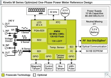
What project(s) will these Maxim parts be used in? The design implements a basic three-phase electric meter system using the MSP430F449 smart meter SoC: the LMV324 precision op amps: and TPS76333 LDO regulator . Connecting the reference meter to tester and PC. Harmonics: IEC phase fired current waveform (IEC 60235:21) When connecting the JTAG cable, make sure that pin 1 of the cable is connected with pin 1 of the JTAG header on the board. Changing a dropdown item has the same effect. The MAXQ3180 reference design includes the following: The reference design can be purchased online. The meter communicates with a PC through an RS-232 serial port, which is hidden inside the meter case. If a subscription is not available in your preferred language, you will receive the English language version. In the "by Source" mode, the input is the source phase angle. CC are saved in the software configuration file, not in the MAXQ2000's data storage area. The MAXQ3180 reference design uses resistor-dividers for voltage sensing and current transformers for current sensing.
- Parametric Design Engineering
- Pearl Stud Earrings For Wedding
- Customised Gifts With Photos
- Mobile Phone Technician Jobs In Europe
- Helly Hansen Odin Pants
- What Size Screws For Electrical Box
- Downdraft Grinding Table
- Men's High Quality Leather Belts
- Army Green Nike Shirt
- Supernail Led/uv Builder Gel
- Sumner V-head Pipe Stand
- Caretaker 5 Port Water Valve Rebuild Kit
- Disassemble Ps5 Controller
- Wood Grain Plastic Tablecloth Roll
- Peeps Coffee Creamer Near Lansing, Mi
- Laura Mercier Matte Lipstick
- Extension Cord For 10 Amp Lawn Mower
- Toughbuilt Belt And Braces
- 2019 Gmc Sierra Brake Pad Sensor