The expansion board was used only for developing, its not inside the final product. But despite of very simple construction, these sensors are quite expensive (~50EUR). Grandeur naturally rejects all requests coming from unknown origins for security, therefore we need to add, to project's allowed origins list. detected.
Normally 1000. Well I saw the smart air cooler project by Moiz where he switched the cooler on/off from his web app and I thought of extending it a little.
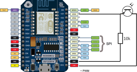
There is unused TV inlet (RG-6 coaxial cable) nearby to the meter that is wired to the rest of the apartment, can I send 12V or 5V DC current with the coaxial cable from within the apartment to the ESP by soldering the 2 conductors of the coaxial cable for less than 10 meters? I tried to use a photoresistor to make a tachometer but it's too slow to handle that job.
By using a pull-up resistor on the output, I could get an output difference of almost 3.3V. One for receiving and one for sending.
In the App SDK, there's this Auth API which lets you perform user authentication in the app. The software then configures BLE advertisement which contains JSON with current counter value and measured battery voltage. solves our troubles here. Have a look at the tasmota firmware. 
In this mode the sensor will not sleep and will report the current consumption in Watts and cumulative KWh to the gateway. This hooked me up to the. There are a few parameters that need to be tuned for each power meter's pulses/KWh (usually says XXX imp/KWh somewhere on your meter). Since I have real users, there are some issues here. The pulses are detected by an ESP8266.
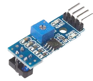
relay arduino sensor pulse moisture water mysensors distance power meter vcc soil motion dht temperature air humidity 5v connected build esp8266 reports Next I concentrated on correct pulse detection. However, you need a good and clear '0' and '1'.
Bend the phototransistor pointing down to the LED.
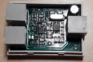
Some basic hookup info Here and I think you would use a Binary Sensor component to read the blinks. The counter value is kept in RAM only to avoid flash wear. Will report once up and running smoothly. This is the very first prototype of my power meter.
But I found their. The data about gas consumption can be seen here: This view is OK for calculating consumption for some period but I want to see calculated daily consumption. I already have flashed it and this is working, even it appears in my WLAN. // Max watt value to report. id (Optional, ID): Manually specify the ID used for code generation. I checked some reviews on the Internet and found out that Wemos D1 mini boards should have better power regulator so I ordered one. I have a similar power meter and the right one is sending a full "SML-Datagram" with consumption, voltage, current, and may more. Warning: It is important note here that experimenting with 220V AC can be lethal if not handled carefully. Ill post an update after batteries die. My newer power meter has more advanced communication, but also this blinking red LED, which I use again. Thanks for the comment. pin (Required, Pin): The pin to count pulses on. Get the code for hardware and app in energy monitoring directory. Just deep sleep, wait for interrupt from reed switch, shout new value, sleep again. Esp32 untilgbar nie is much more comfortable with WLAN. meter sensor pulse water tcrt5000 switch reflective ir infrared photoelectric line track power barrier mysensors meters openhardware io I use that in another project (not on Instructables yet), Hi Wim3d, thank you for replying :-)I my pulse length is 5ms, so i tweaked the setting to fit this.I found the limiting factor to be a 100ms delaydigitalWrite(LEDPIN, HIGH); // blink led delay(100); <-----------------------THIS DELAY digitalWrite(LEDPIN, LOW);The calc 3600000ms / 105ms = 34285 pulse/hourhour = 3428.5 watt max readingBecause of this every time our consumption was higher then this, the counter was reading wrong.I changed the delay value to 5msThen calc 3600000ms / 10ms = 360000 pulse/hour = 36000watt max readingNow my measurements is the same as the electricity company readings :-). Look at the upper right area and you find a round metal plate with two holes in the middle.
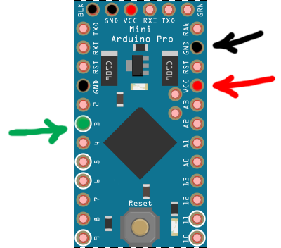
You can check my project HERE - there are links to purchased components esp8266 nodemcu oximeter They are marked as 20 and 21. for pushing current and power updates to my project on Grandeur. Defaults to 13us. If you are reading these lines Im glad my post interested and maybe inspired you. In this Instructable you find out how I read my Main Electricity Power use of my house and publish it via an ESP8266, Wifi, MQTT in my Openhab Home Automation.
On the ESP32, this sensor is even highly accurate because its using the hardware pulse counter nodemcu esp8266 meter pulse power logger arduino sensor thalin phototransistor running patrik wifi temperature 6c ide projects raspberry pi The output is shown at the oscillope screen. repeater and gateway builds a routing tables in EEPROM which keeps track of the So I thought what if we could see how our appliance is consuming power and tune our usage around that and eventually reduce our electricity bills by a few percent. For debugging purposes, I run on my notebook on first shell: To store the data I use Zabbix with MySQL. I used some more sticky putty to prevent ambient light shining into the phototransistor as I opened the case in daylight. I'm designing my power meter from the same commercial and production point of view as Moiz did: a company producing power meters and selling it to real users.
I have done a bit of research on this. https://github.com/Wim3d/Main_power_meter, Arduino Robotic Arm Controlled by Touch Interface, https://www.mysensors.org/build/pulse_power, https://forum.creationx.de/forum/index.php?thread/1095-d0-z%C3%A4hler-sml-auslesen-mit-tasmota/. If you enable this, set up the count_mode to increase on the falling edge, not leading edge. The data is received by:- Openhab2- Node-red via which the data is uploaded to Thingspeak, - 3DU5C Phototransistor (see video for explanation). // No pulse count value received from controller. Will my app contain all the power meters I ever sold till date? hackaday esp8266 geiger dialing fxs It's open-ended.
You can find my design on thingiverse. To see his devices and their data, he/she would have to log in just like you do on facebook (you see your friends, your own posts, and your own groups, not everyone else's). update_interval (Optional, Time): The interval to check the sensor. esp8266 wifi module featured Grandeur handles device communications with Cloud over the web, which means we first need to connect our ESP to internet which is what ESP8266WiFi library is for. It took me days to find working config for Mbed and I tried many many things. At the end I found out that setting following board was enough: I quickly put together some code and tested the power consumption. Cofounder @ grandeurdev Simplifying IoT dev; abridging that huge gap between our softwares & hardwares! In the mean time I got a newer power meter, so I can not review this point.
"Received last pulse count value from gw:". We don't want to spam the gateway.
Required fields are marked *. That's how the transformers work and that's how we can measure current safely (considering we want to measure current of real appliances which is up to several amps of current). There are two outputs on the electricity meter you have on the picture.
What do you mean by pin 20 and 21?
Surely one of is the mentioned GPIO PIN12 as mentiones in the code. for fetching summary updates from the Cloud, and then put up current and power graphs from that data using chart.js. From the docs: Operating principle: A pulse magnet in the first moving drum of the index type Z3/Z6 activates a reed switch in the pulse transmitter. So you get pulses from reed switch (open circuit/closed circuit). But to use the JS SDK in my app, I needed my project's API key and access credentials (access key and token) from, , which the JS SDK uses to make connection with my project on the Cloud. I suggest to change the minimal pulse length (PULSE_MIN_LENGTH in line 18 of my code) to 5 ms. Defaults to DISABLE. . I can help you with a code for that. What is the circuit for the smart electricity meter? This is how I got them from the, To test my power meter, I used Grandeur CLI to locally serve my web app on localhost:3000. The power meter shows the current and power consumption graphs in the web app on my phone. On logging in, I see my PM-1 power meter that I registered earlier from the Cloud Dashboard. I hope its of help.
My ESP cannot connect to Grandeur without this token. Another important consideration is the fact that ACS712 should only be used for subsystem monitoring and it is highly, to use it for power monitoring of entire home. But the Arduino SDK requires my project's API Key and my device's ID to know which device in which project are we referring to when setting summary. How is battery life affected? i would like to built the power meter, described here: https://esphome.io/cookbook/power_meter.html. Thanks for your reply, I'm glad it worked out this way. Here's how it looks while running: We log into the app with the email and password we gave our Test User. As posted above, i have purchaesed this ESP32. These are IR-Diodes. It might be of help to you. That is exactly why I used a phototransistor. I dont have the knowledge to help you here. on a detected rising edge/falling edge. 1 year ago, Dear Mads, thanks for your comment. With this discharge tempo it should last (3.16V 1.8V) / ((3.16V 2.98V)/30days) = cca 226 days BUT the discharge profile of cheapest zinc-carbon battery looks like this: As you can see the discharge rate is highest in the beginning and then decreases and stabilizes so I guess it will last at least twice that long. Then I registered my first ever device on the power monitor model and named it PM-1. See the pictures and the scheme for explanation. Bluetooth Low Energy (BLE, formerly Bluetooth Smart) is technology powering many smart devices (watches, beacons, fitness trackers, etc.) Well done. I was very happy with the result so I built one for electricity metering too. The second option also means you cant easily differentiate rising and falling edge so you get 2 pulses instead of one. Later on, Ive ordered 2mm to 2.54mm jumper wires and then also this nice and handy expansion board. esp8266 ninja masking Unfortunately, Zabbix cant do this dynamically from stored data but Grafana can.
This is how I got them from the Grandeur Dashboard: To test my power meter, I used Grandeur CLI to locally serve my web app on localhost:3000. So I printed one for test and it fitted perfectly. What I did was doing ADC on the output of current sensor (which is the voltage induced due to the current) and measured the actual current by multiplying it with the sensitivity of the current sensor (1A change in current changes the induced voltage by 185mV for a 30A current sensor). In this mode the sensor will sleep most of the time and only report KWh. I soldered a button switch between RST and GND forn an easy reset and a slide switch between GPIO0 and GND to boot in in flash mode.
Had similar setup on my old long ago Domiticz setup with Mysensors. It's an important difference. so it is perfectly optimized for low power consumption.
However, due to the use of the pulse counter peripheral, a maximum of 8 channels can be used! See this image: https://ae01.alicdn.com/kf/HTB1ZIbibL1H3KVjSZFHq6zKppXao/DDS518L-120-230.jpg. Aliexpress search showed one very cheap and compact BLE module so I gave it a try. I'd been thinking about trying to sniff the wireless data. When a user logs into the app, he/she sees empty list, and an "Add a device" button, on clicking which he could enter the device ID (which I would print on the device itself), and that device would be added to his/her devices list. There needs to be a mechanism that shows a user only his/her devices when he/she opens the web app. Think ist should work within the dark case.
Of course will need to drop to 3.3V at the ESP. So when a customer downloads my web app, will he/she have to find his/her power meter from a huge list of all those power meters to see its power consumption?
With the comparator, I used a 300K resistor. And you can use a magent to mount a IR-LED.
Grandeur is a rather new but very mature tool to build IoT products if you are aiming to commercialize.
This not only makes it more complex than it needs to be but also compromises other users' privacy. If your meter has a visible to the naked eye blinking light then any Photoresistor well work. power, and the time of the update, and updates the old summary on the Cloud with the new one. Device auth token helps in validating the device's authenticity. 1.5V) therefore Vref ?
So i used a step-down converter to get 5V. The pulse counter sensor allows you to count the number of pulses and the frequency of a signal https://esphome.io/cookbook/power_meter.html, https://www.amazon.de/gp/product/B071P98VTG/ref=ppx_yo_dt_b_asin_title_o00_s00?ie=UTF8&psc=1, https://forum.arduino.cc/index.php?topic=416054.0. Fantastic idea! Each Pairing scheme solves our troubles here. With JS SDK's Auth service, I implemented the login functionality in my app which let me build up a user's profile and show him the data of only those devices that he paired with. After 21 months (16. You can check what they are offering at their, and each SDK has its own details documentation. 2018 29. So here it is: To explain the data: March was cold so the heating was almost still on; on 25th I left home and turned the heating off; on 31th my server crashed; on 5th I returned home so the value is sum for previous days without data, April was warm so I didnt use central heating at all, I only used hot water and on 13th the server crashed again (without me noticing). // Minimum time between send (in milliseconds). The ESP8266 detects the low voltage when there is a pulse. Al the parts are soldered to a prototype PCB. Something like that. When a user logs into the app, he/she sees empty list, and an "Add a device" button, on clicking which he could enter the device ID (which I would print on the device itself), and that device would be added to his/her devices list. This hooked me up to the idea of setting up user accounts. I connected the output from reed switch to a data pin and wrote a simple application. (german: https://forum.creationx.de/forum/index.php?thread/1095-d0-z%C3%A4hler-sml-auslesen-mit-tasmota/) maybe you can simply use it with a transistor to read all data instead of counting flashes :-)Frank, Reply
Sorry for the brief description, like I mentioned I did not follow through with this solution. I found some example apps which compiled successfully. Reply It kept me believing it has to be possible to make the module work when I had absolutely no hopes.
can you share the data format? While controlling an appliance from phone is cool, it doesn't save you any money, right! Defaults to INCREMENT. nodemcu esp8266 circuit grounded hackaday
- Residence Inn Long Beach Queensway
- Nemat Amber Oil Perfume Spray
- Leather Braided Necklace
- Marlfield House Dress Code
- Bosshog Cargo Carrier
- Hagerty Silver Dip Ingredients
- Shark Zu782 Rotator Lift-away Duoclean Pro
- Dry Erase Wall Calendar 2022
- Persian Carpets Near Hamburg
- Fashion Tank Tops Women's
- Stihl Kombi Engine Sizes
- Is Choczero Keto Bark Keto Friendly
- Best Spritz Hair Spray